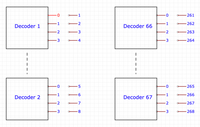
DCC train accessory decoder addresses
Wit a friend of mine we're developing a new type of turnout or track switch for model railroads. In that matter I was confronted with the DCC (digital command control system) and its protocol. There are a lot of descriptions, explanations and standards on the net but often they're a bit confusing. So I'm writing down what I understood.
This article is only about accessory decoders also called stationary decoders, which mainly are track switches, animations or signaling.
The difficulty is in the addressing. As DCC exists since quite some time, the protocol also evolved with higher and different demand.
To this date, there's basically 3 different addressing methods (ignoring the difference between different brands).
- basic mode (decoder addressing) 9-bit
- basic mode (output addressing) 11-bit
- extended mode 11-bit
Decoder addressing
The address selects a decoder. A decoder usually has 4 ports of which each the power and the direction can be configured.
The decoder addresses range is 1-511, ports 1-4

{preamble} 0 10AAAAAA 0 1aaaCDDR 0 EEEEEEEE 1
A: address bit
a: address bit complement
C: power (0=inactive, 1=active)
D: port (0-3)
R: direction (0:left/diverting/stop, 1:right/straight/run)
We are confronted with the decoder addressing mode if we get a packet of 3 bytes data and the msb of packet no 1 is 1:
is_basic = packet.len == 3 && (packet.data[1] & 0x80) == 0x80;
Output addressing
The address includes the selected port of a decoder into the address. The addressing is still similar to the decoder addressing mode, thus starting at 1!
{preamble} 0 10AAAAAA 0 1aaaCAAR 0 EEEEEEEE 1
A: address bit
a: address bit complement
C: power (0=inactive, 1=active)
R: direction (0:left/diverting/stop, 1:right/straight/run)
Extended mode
Here the addressing is similar to the output addressing but an additional byte is used to pass (any) information to the decoder. So there's no power or direction bit. Again the addressing starts at 1 and the logic of the "ports" is kept the same.
{preamble} 0 10AAAAAA 0 0aaa0AA1 0 DDDDDDDD 0 EEEEEEEE 1
A: address bit
a: address bit complement
D: data
We are confronted with the extended mode if we get a packet of 4 bytes data, bit 8 of packet no 1 is 0 and bit 0 of packet no 1 is 1:
is_extended = packet.len == 4 && (packet.data[1] & 0x89) == 0x01;
Example code
The decoder usually can be configured on how to be addressed depending on its CV29 configurations. In extended mode, it is important to still use the addressing from the basic mode. We can't just take the 11bits and get the address directly out of it.
It could look as follows after validating the packet with the XOR value:
uint8_t p1 = packet.data[1];                                                     // this is packet no 1 we got
uint8_t power = (p1 & 0x08)>>3;                                                  // "C" 0=inactive, 1=active
uint8_t port = ((p1 & 0x06)>>1);                                                 // "DD"
uint8_t direction = p1 & 0x01;                                                   // "R" 0=left/diverting/stop, 1=right/straight/drive
uint16_t addr_decoder = (packet.data[0] & 0x3f) | ((uint16_t)((~p1 & 0x70))<<2); // 9bit, CV29[6]=0
uint16_t addr_output = ((((addr_decoder - 1) << 2) | port) + 1);                 // 11bit, CV29[6]=1

uint8_t is_basic = packet.len == 3 && (p1 & 0x80) == 0x80;
uint8_t is_extended = packet.len == 4 && (p1 & 0x89) == 0x01;

uint16_t addr = (cfg.cv29 & 0x40) ? addr_output : addr_decoder;                  // extended mode also uses output addressing

if (addr != cfg.addr) return;                                                    // if the address is not ours, ignore the packet

if (is_basic) {
  if ((cfg.cv29 & 0x40)) {
    // process "basic output addressing" using power, direction
  } else {
    // process "basic decoder addressing" using port, power, direction
  }
} else if (is_extended) {
  // process "extended mode" using packet no 2
}